Install i-refactory modeller
In this section we will guide you through the installation of the i-refactory modeller. The i-refactory modeller is based upon a combination of specific PowerDesigner configuration and installation of our extensions.
Supported Power Designer Releases
The following PD versions have been tested and are officially supported:
Release 16.5
- 16.5 SP03 PL02
- 16.5 SP03 PL03
Release 16.7
- 16.7 SP02 PL01
- 16.7 SP07
Other releases or service packs will most likely function without problems. However, we do not offer official support. Use other releases and service packs at your own risk.
We advise to not use PD 16.7.0 and PD 16.7 SP02 (without the PL01 patch) since these releases introduced undocumented compatibility issues with our extensions.
This install instruction guides you through installing PowerDesigner and configuring PowerDesigner.
{tip} It is important to carefully follow the installation instructions in the following sections.
Step 1. Install SAP PowerDesigner
First, you need to get a valid license of SAP PowerDesigner Data modeller. Then, follow the install instructions of SAP PowerDesigner.
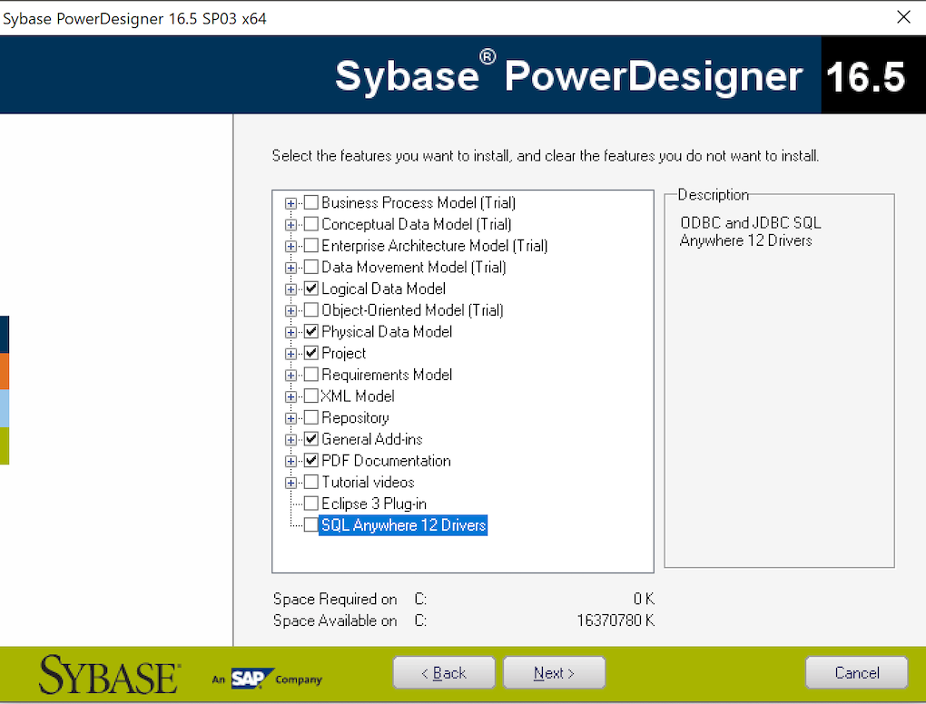
When installing SAP PowerDesigner Data Modeller you should at least select the following components:
Step 2. Unpack the i-refactory modeller add-ons
The i-refactory modeller add-ons are shipped as a zip-file., which contains the following folders:
- i-refactory-modeller
- dbms
- extensions
- model-templates
- models
- settings-sets
You should unzip the content to your HOME folder or to a shared folder on your local machine. We will refer to this install folder in the next paragraphs as I-REFACTORY-MODELLER-PATH.
{info} Remember the folder where you have copied the i-refactory modeller add-ons, as you will need this location later.
Step 3. Change General Options
PowerDesigner pre-ships with some default settings in General Options. In the following, we show how some of these default settings should be changed.
-
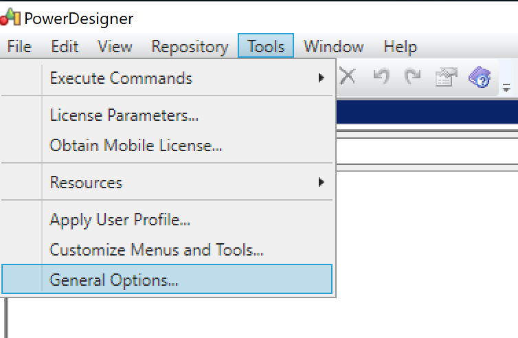
Open the General Settings as shown in the figure below.
-
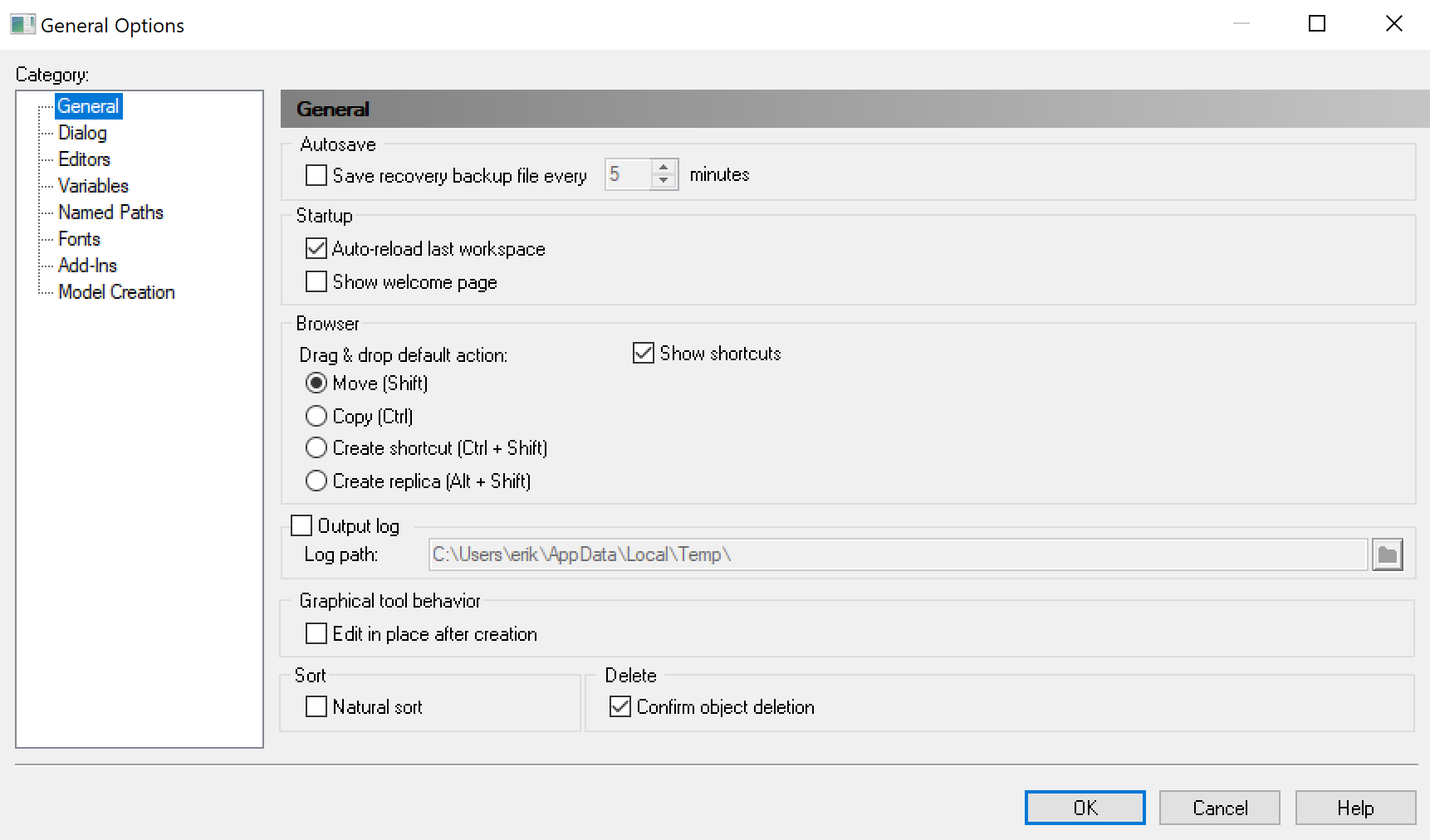
Change the General settings.
-
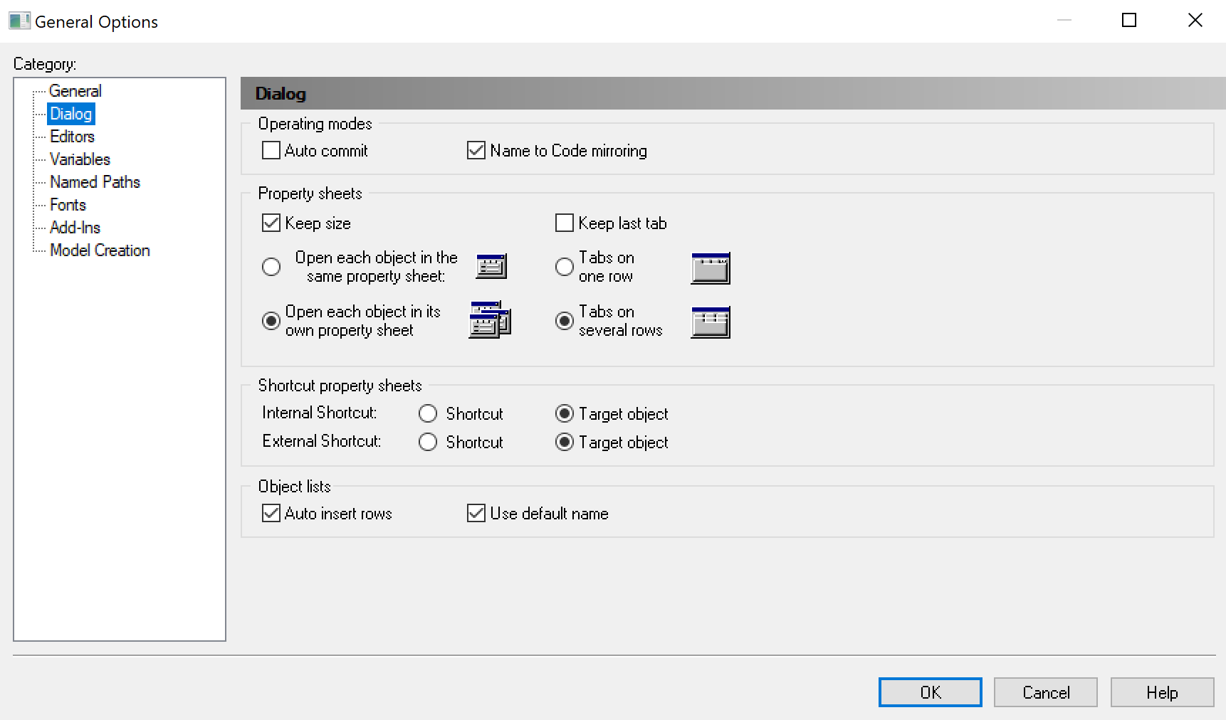
Change the Dialog settings.
-
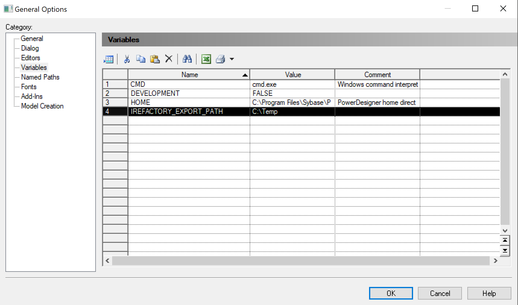
Create Variables.
When we export the DDL and metadata, we need a default path where we should create the results of the export. Create a variable with the name as shown in the figure below and assign a valid path value. In the figure below we set the value to "C:\temp".
-
Create Named Paths.
Each time when PowerDesigner saves your models as .pdm files, it saves the filepath of any referenced files or models. For example, the extension files used, shortcuts to other models, etcetera.
If someone else — on a different computer — opens your models, this might result in references to files that cannot be found on that computer. By creating named path variables PowerDesigner replaces the string as set in
Pathwith the name of the named path variable. This reduces the issues of not being able to find these files.To enable this capability of PowerDesigner, you need to create two named path variables exactly as shown in the two selected rows in the figure below.
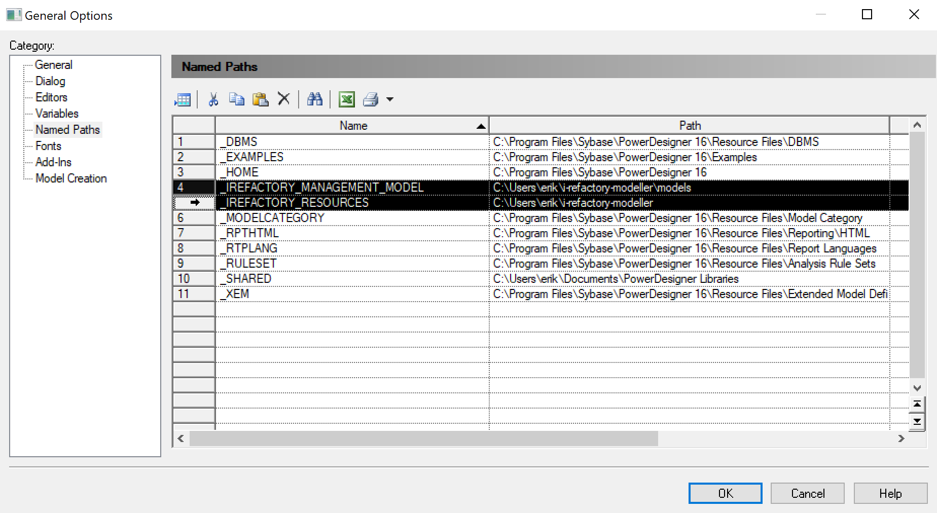
PowerDesigner create named path variables The value for the named path variable
_IREFACTORY_MANAGEMENT_MODELshould be set toI-REFACTORY-MODELLER-PATH\models.The value for the named path variable
_IREFACTORY_RESOURCESshould be set toI-REFACTORY-MODELLER-PATH.{info} Create the named path variables exactly as shown, beginning with an underscore and in capitals.
-
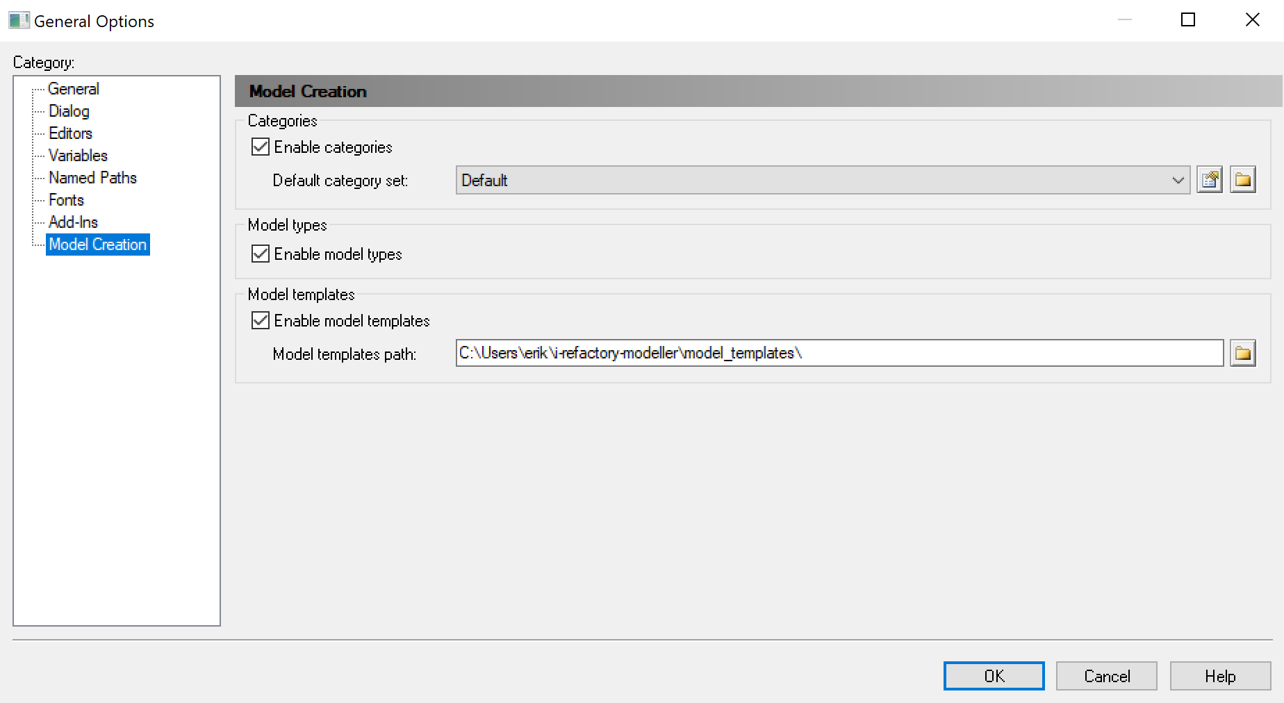
Configure Model Creation.
The i-refactory modeller add-ons contain default templates for the various models you can create. These templates have pre-configured settings. For example, the proper attachments of required extensions.
To enable model creation with templates, you need to configure the path to these model templates and enable its usage.
Set the path value to
I-REFACTORY-MODELLER-PATH\model_templates. -
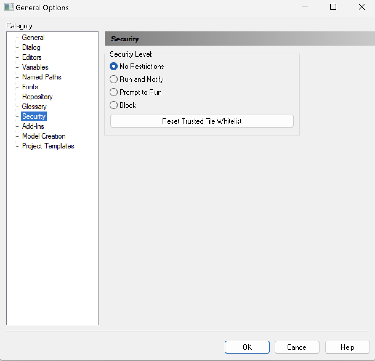
Configure Security.
Dependent on the specific version of PowerDesigner, you have the possibility to make settings for Security. When this section is available, make sure you follow these instructions.
The i-refactory modeller add-ons can be used without user(s) have to confirm it every time Power Designer is opened by ensuring the following security-setting is made :
Set security level value to
No Restrictions.
Step 4. Configure DBMS resources
PowerDesigner needs to be aware of the filepath of custom resources. As the i-refactory modeller add-ons contain custom resources for the DBMS, we need to configure the filepath for these resources.
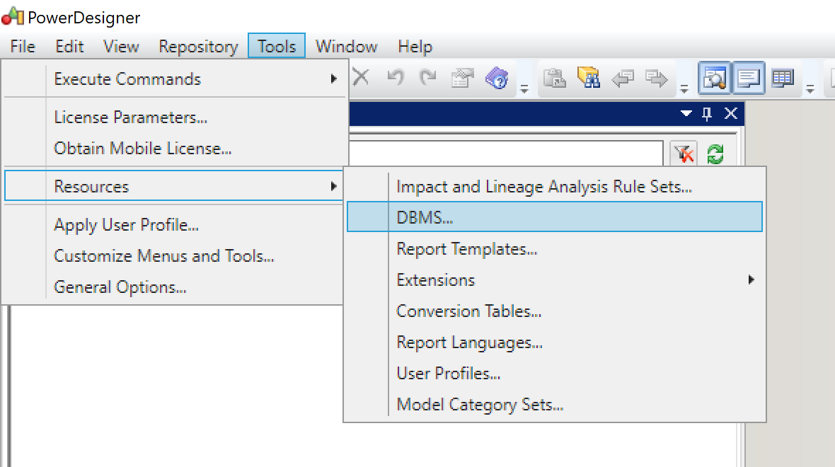
-
Open the menu to change the settings for the DBMS resource.
-
Click the path icon in the window shown.
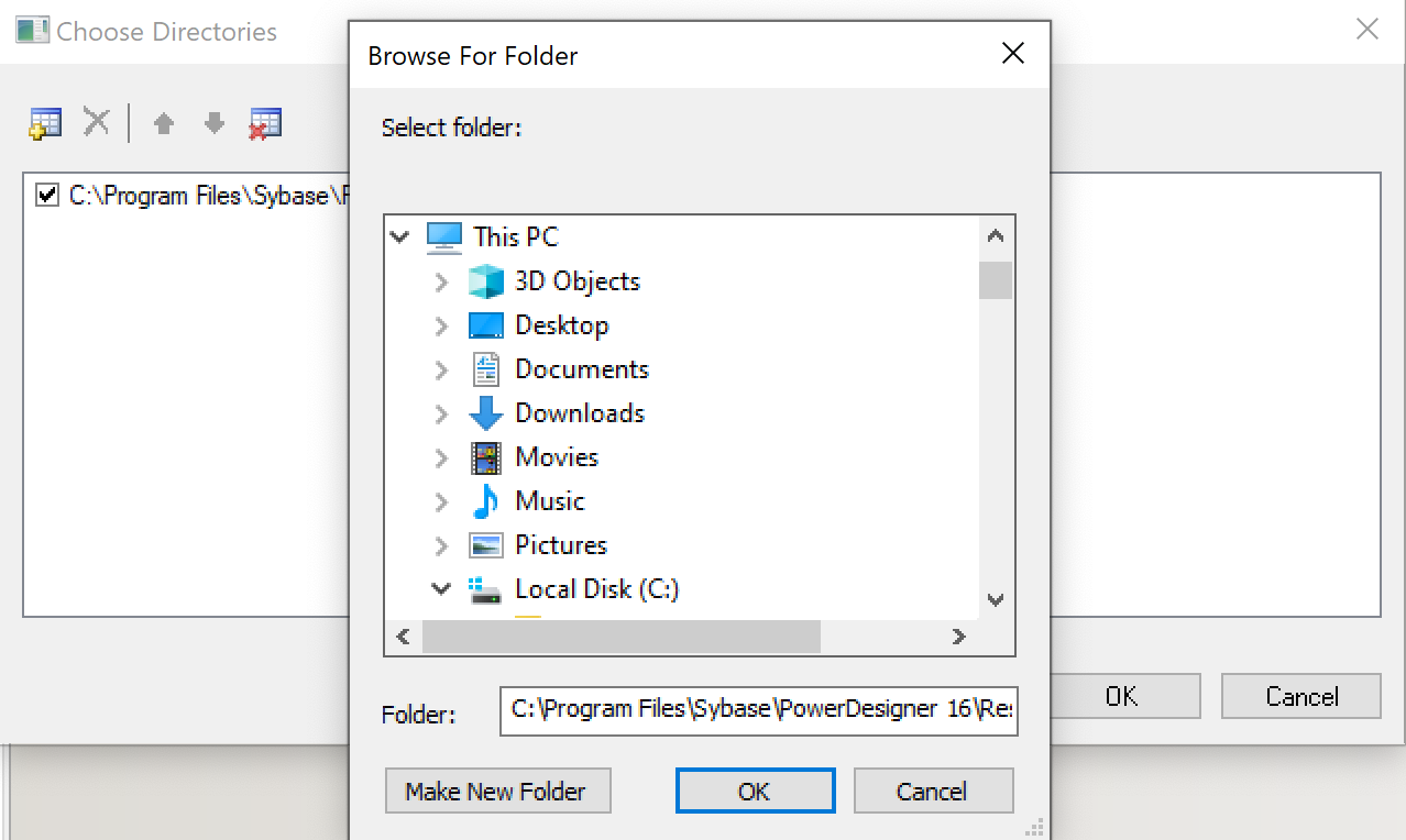
-
Next, you will need to add an additional directory. You can do so by clicking the add icon.
This opens a browser to your local file system. Select the directory
I-REFACTORY-MODELLER-PATH\dbms. A new directory is now added to the list of directories. -
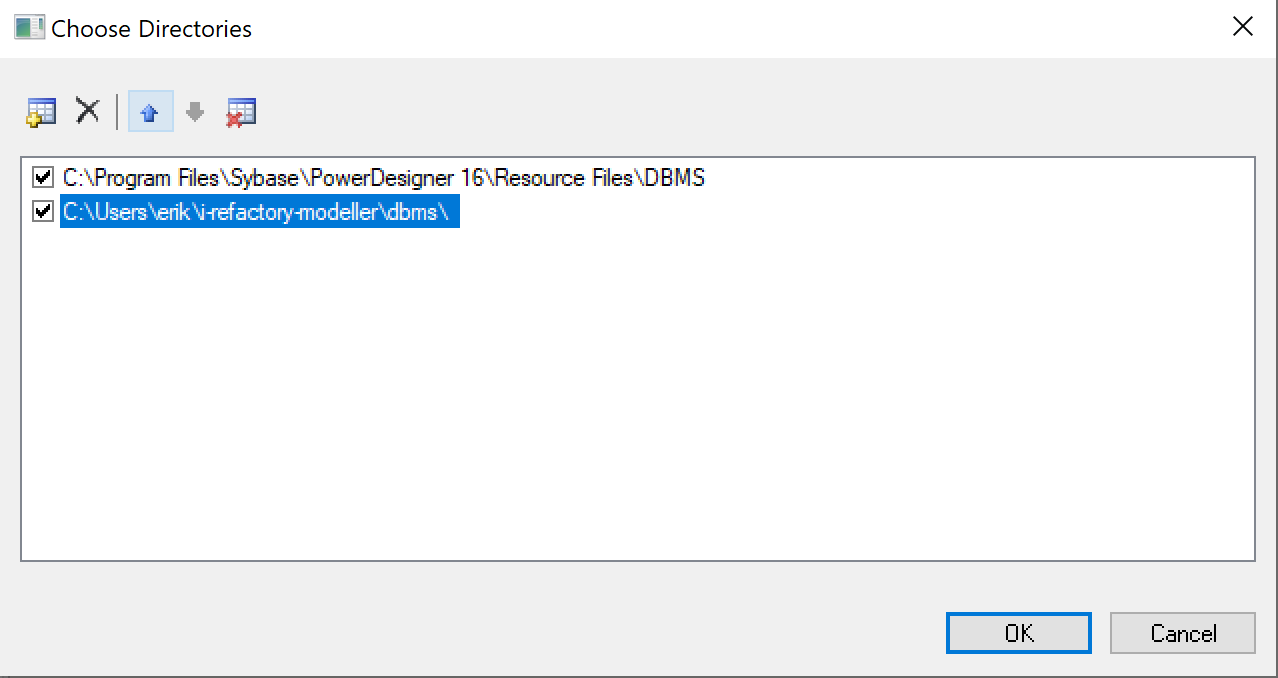
Make sure the new added directory is on top of the list by clicking the move-up button.
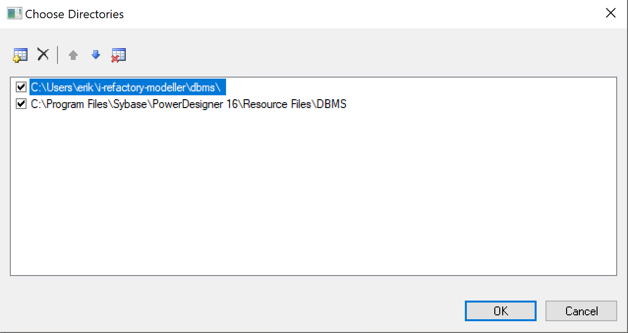
-
You have finished adding the DBMS resources and you should now have a configuration as shown in the figure below.
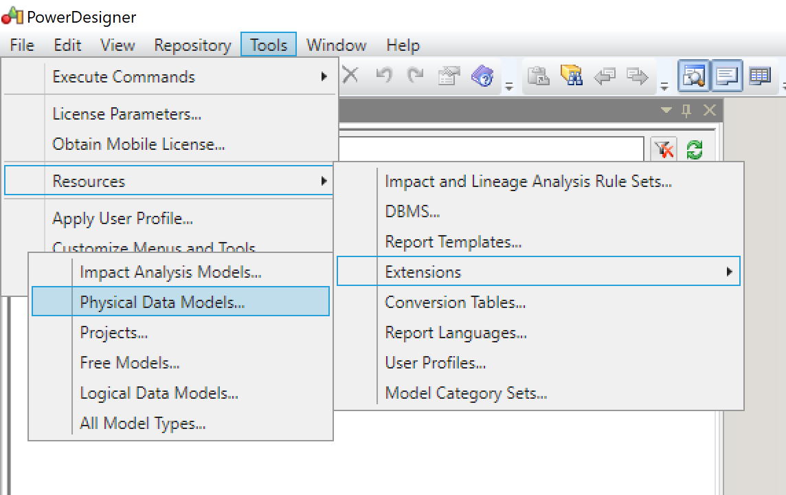
Step 5. Configure Physical Data Model resources
-
Open the menu to change the settings for the Physical Data Model resources.
-
Click the path icon in the window shown.
-
Next, you will need to add an additional directory. You can do so by clicking the add icon.
Select the directory
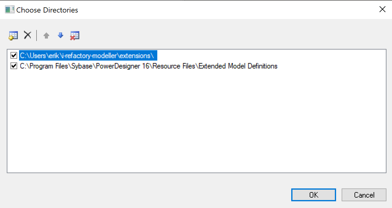
I-REFACTORY-MODELLER-PATH\extensionsfrom the file system browser. A new directory is now added to the list of directories. -
Make sure the new added directory is on top of the list by clicking the move-up button.
-
You have finished adding the Physical Data Model resources and you should now have a configuration as shown in the figure below.
Step 6. Configure DBMS and Settings Sets
When you create a physical data model in PowerDesigner you can choose the DBMS for which you are creating the physical data model.
We need to set the default DBMS to SQL Server.
-
First create a new physical diagram
Menu > File > New Model > Model Types > New Physical Model > Physical Diagram. -
Change the DBMS for the physical model.
Menu > Database > Change Current DBMSFrom the drop down menu pick the option
Microsoft SQL Server 2012 - 1.4.4.0as shown in the figure below.
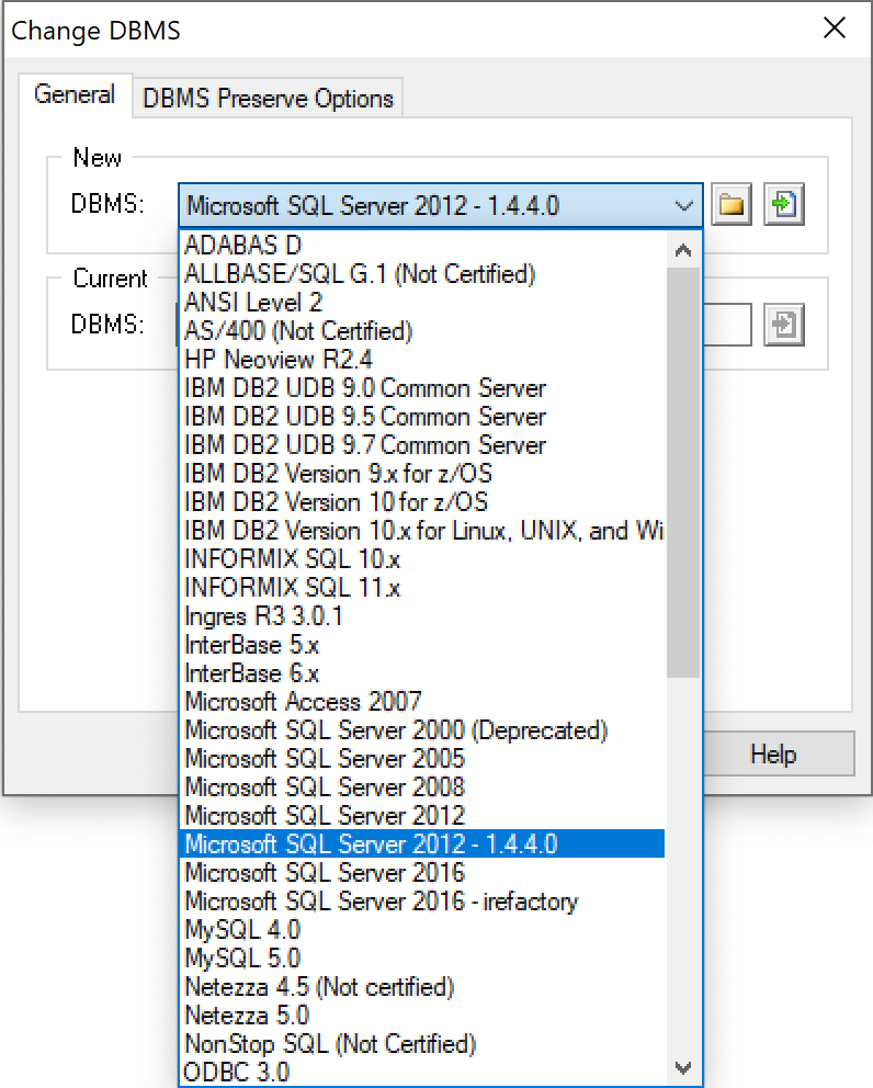
From now on this will be your default DBMS when you create a new physical model.
Step 7. Configure Settings Sets
When you create a physical model, PowerDesigner is capable of generating the proper Data Definition Language code, in short DDL. You can change the behaviour of the DDL generation. For example, for which object types to generate DDL and for which object types not to generate DDL.
We have provided default templates for these settings. These templates and their settings are important. This is because of our design choice to not implement all model object types in the database.
{info} Although this is out of scope for the installation guide an example will help in understanding the above mentioned design decision. In a technical staging model, you have the option to create a primary key on a table. This metadata information will be used in our code generation. However, when we implement a technical staging model, we do not want to create a unique primary key constraint in the database as this might result in loading errors when the table is populated. In the settings set configuration, this is exactly what we can do: ignore the creation of certain DDL statements.
-
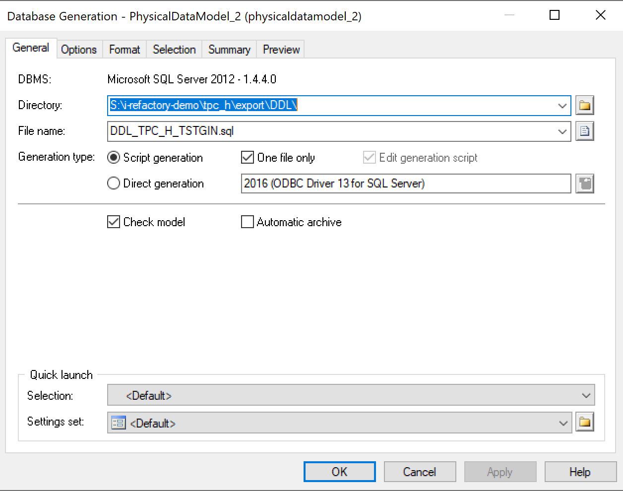
Open the menu.
Menu > Database > Generate DatabaseThis will open the dialog as shown in the figure below.
-
Click the file icon in the lower right of the dialog.
This will open a file browser as you have seen earlier in this install guide.
Select the directory
I-REFACTORY-MODELLER-PATH\settings-sets.
Step 8. Validate the installation
-
Shutdown your PowerDesigner application.
You do not have to save anything so you can safely answer
nowhen you are asked to save. -
Open the PowerDesigner application again.
-
Create a new model
We are going to create a new physical model based on the templates we have provided.
Menu > File > New Model > Templates > Technical Staging model > OK{info} When a message "Could not find the management model, is it opened?" is shown click OK.
When all sorts of errors are shown, keep in mind that PowerDesigner 16.5 uses Visual Basic Script. This is part of the .NET framework. You'll need .NET framework version 3.5 to work with this PowerDesigner version. You can find more information about .NET framework version 3.5 for Windows 10 here: Install Framework. Restart Windows, restart PD and these errors should be gone.
A new physical model is created in PowerDesigner.
-
Check settings
Check the following settings:
-
Menu > Database > Change Current DBMSThe value for current DBMS should be
Microsoft SQL Server 2012 - 1.4.4.0 -
Menu > Database > Generate DatabaseThe value for settings set should be
Generate technical staging -
Object browser > Open Extensions folderA list of at least 6 extensions should be present, all beginning with
i-refact -
Menu > Tools > General Options > Named PathsThe named paths, should be present (as created in Step 3. Change General Options - Create named paths)
-
Installation completed
If all the settings are ok, the installation is correct and you can start modelling.
To have an overview about how i-refactory modeller works, you can go to i-refactory modeller overview.