How to create a logical validation model
In this section we explain the steps you need to follow to create a logical validation model (LVM) from scratch. The main assumption is that you understand the business data request (the Need) and you performed a source analysis (the Supply). In another section we explain how to generate a logical validation model from an existing LDM (Logical Data Model).
- Step 1. Adding an empty model
- Step 2. Creating entities
- Step 3. Adding references
- Step 4. Creating subtypes and generalizations
- Step 5. Adding advanced constraints
- Step 6. Creating mappings
- Step 7. Preparing for delta-loads
At any moment, you can perform a model check to verify if there are errors in the model.
Example
The logical data model and the technical staging model below are used as an example to illustrate the logical validation model concepts and to explain the steps for creating a logical validation model. It represents entities and relationships of the TPCH benchmark.
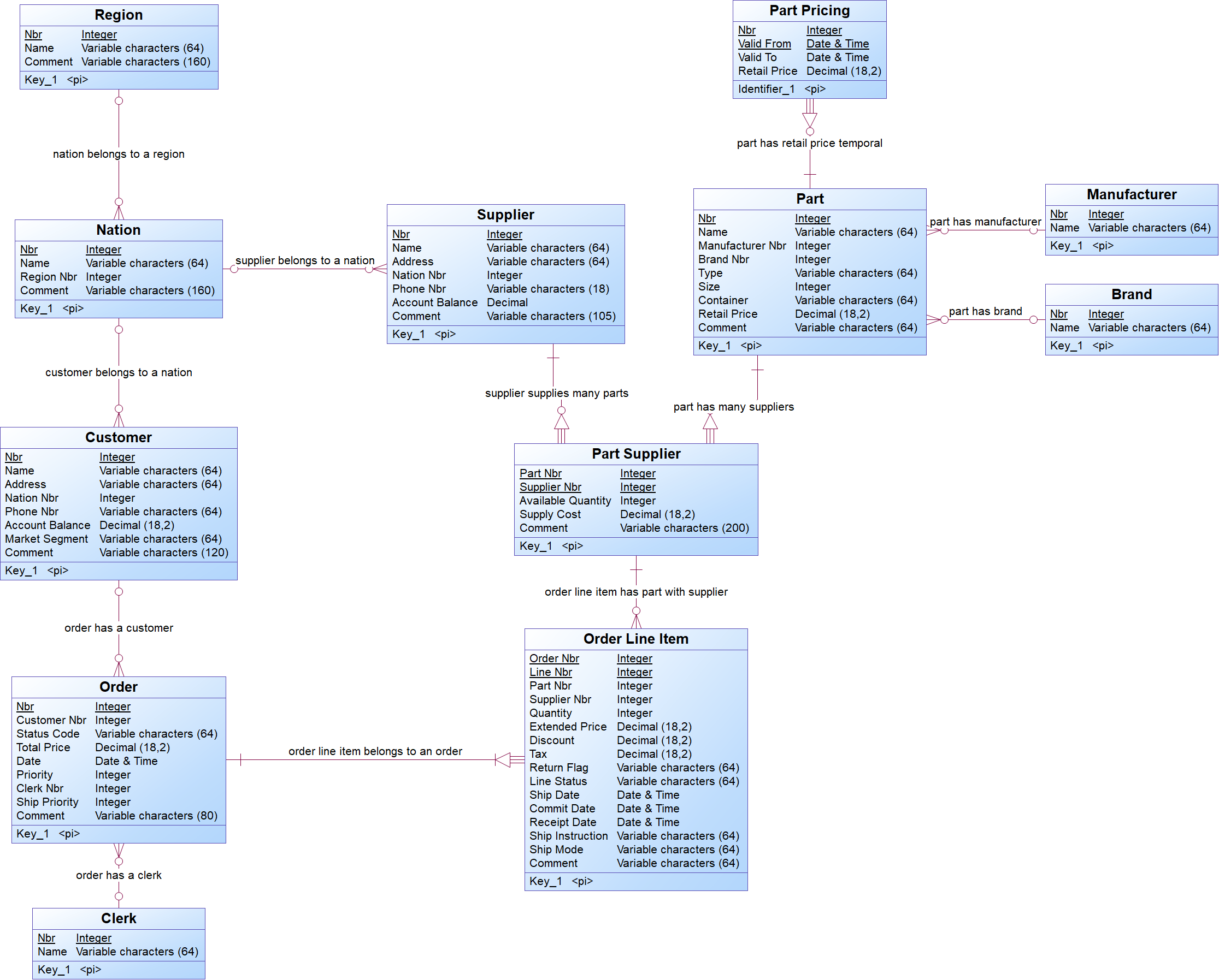
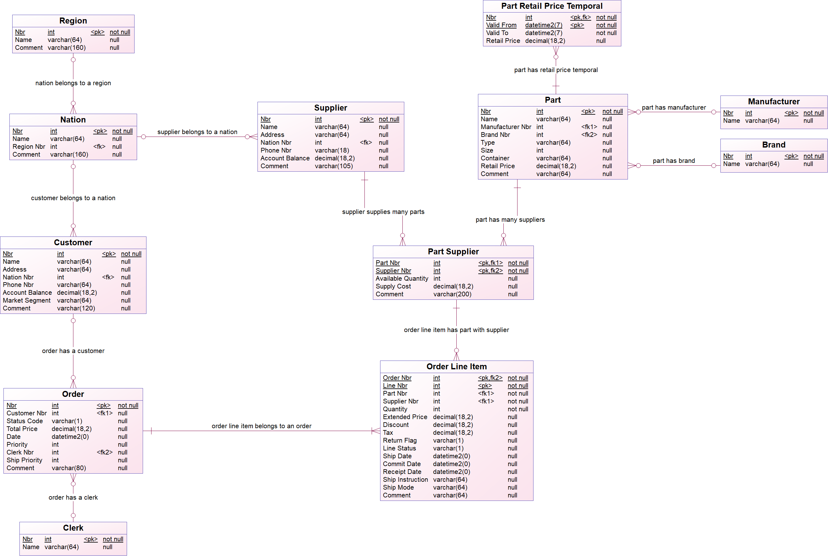
The TPCH logical data model:
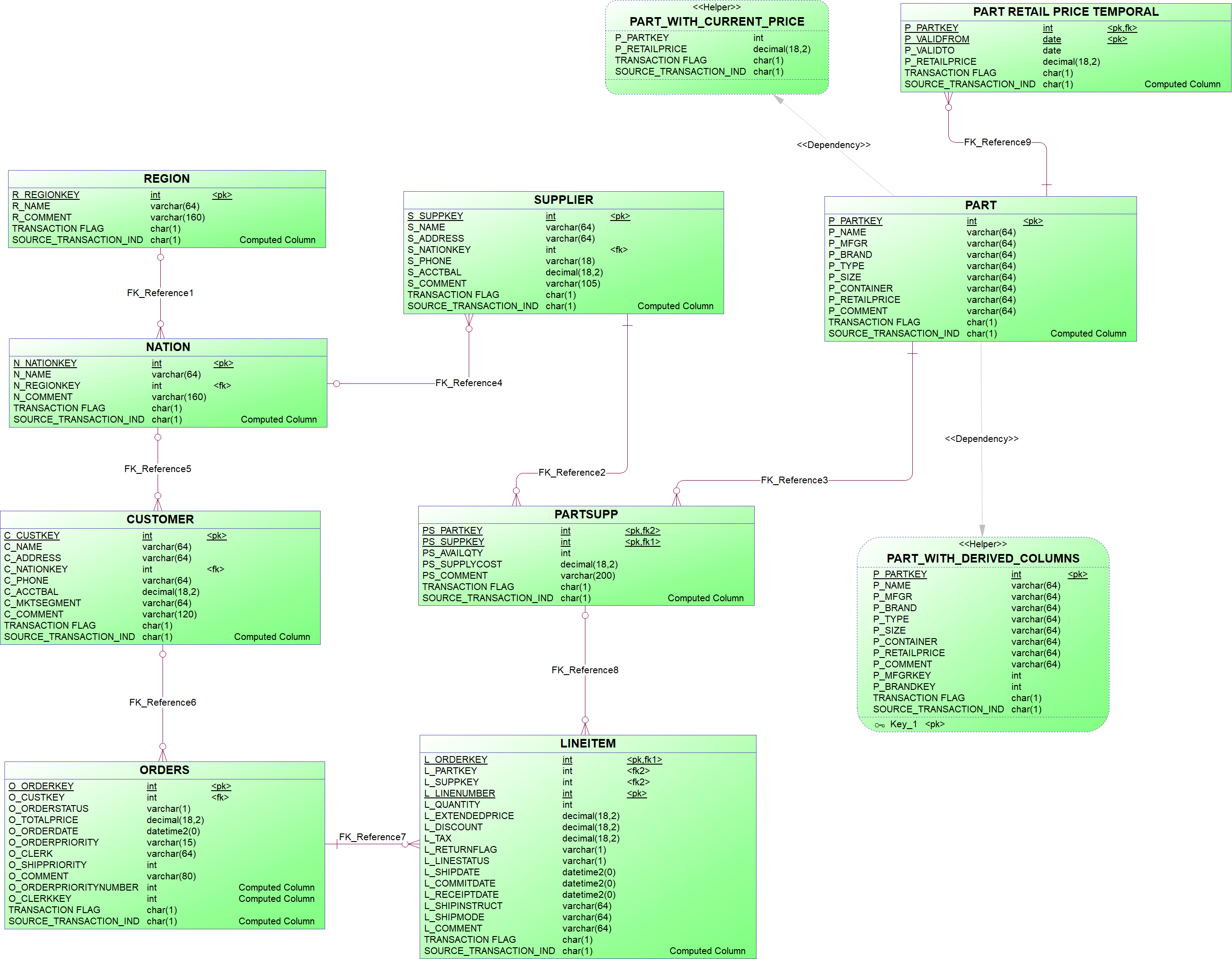
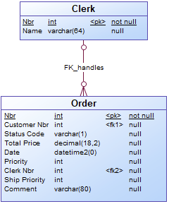
The TPCH technical staging model:
Before you begin
Before you begin to create a logical validation model for a specific technical staging model you should analyze the technical model (the Supply) and how it is related with the business requirements (the Need). Based on this knowledge, you identify the entities, references between entities and constraints of the logical validation model.
Identifying entities
When the technical model already meets the business requirements, then the logical validation model will be a copy from the technical model. For each entity in the technical model, you add a corresponding entity in the logical validation model.
When there is no one to one correspondence between the entities in the technical model and the concepts from the business requirements, then you need to identify the concepts from the business requirements, whose instances can be obtained from entities of that specific technical model. For each identified concept, you add an entity in the logical validation model. It is possible that one entity in the technical model corresponds to multiple concepts. In the logical validation model, this entity is normalized to reflect the business requirements.
It is possible that the naming of entities and attributes in the technical staging model already match the naming of the business concepts, but it is also possible that the technical staging model uses different naming conventions. In the last case, you need to adjust the names.
{example} In the TPCH logical data model, brand and manufacturer are seen as concepts, but in the TPCH technical staging model, brand and manufacturer are attributes from the entity Part. To reflect the business requirements, in the corresponding logical validation model, the entity Part is normalized and two new entities are created: Brand and Manufacturer. When data flows from the Technical Layer to the Logical Validation Layer, the entities Part, Brand and Manufacturer are populated with data coming from the entity Part in the technical staging model.
In a similar way, Clerk is seen as a concept in the logical data model, but in the technical model is represented as an attribute from the entity Orders. To reflect the business requirements, in the TPCH logical validation model, an entity is created for the concept Clerk.
Identifying references
References between entities in a logical validation model can be identified from the references between entities in the technical staging model, when available, but also from the relationships between entities specified in the business requirements.
Relationships one-to-one (1:1) and one-to-many (1:N) between two entities are represented as references in the logical validation model. For relationships many-to-many, an associative entity is created in the LVM with a reference between the associative entity and each one of the entities from the relationship.
{example} In our example, consider that there is a one-to-many (1:N) relationship between Region and Nation, which means that a region may have multiple nations, and one nation belongs to only one region. This relationship is represented in the LVM as a reference between the entity Nation and the entity Region.
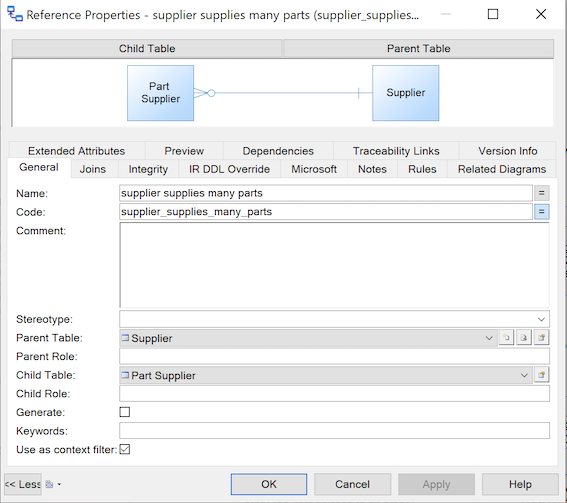
The relationship between Part and Supplier is a many-to-many (N:M) relationship, which means that a part may have multiple suppliers and a supplier may supply multiple parts. This relationship in the LVM is represented with an associative entity, called Part Supplier, and one reference between Part Supplier and Part, and another reference between Part Supplier and Supplier.
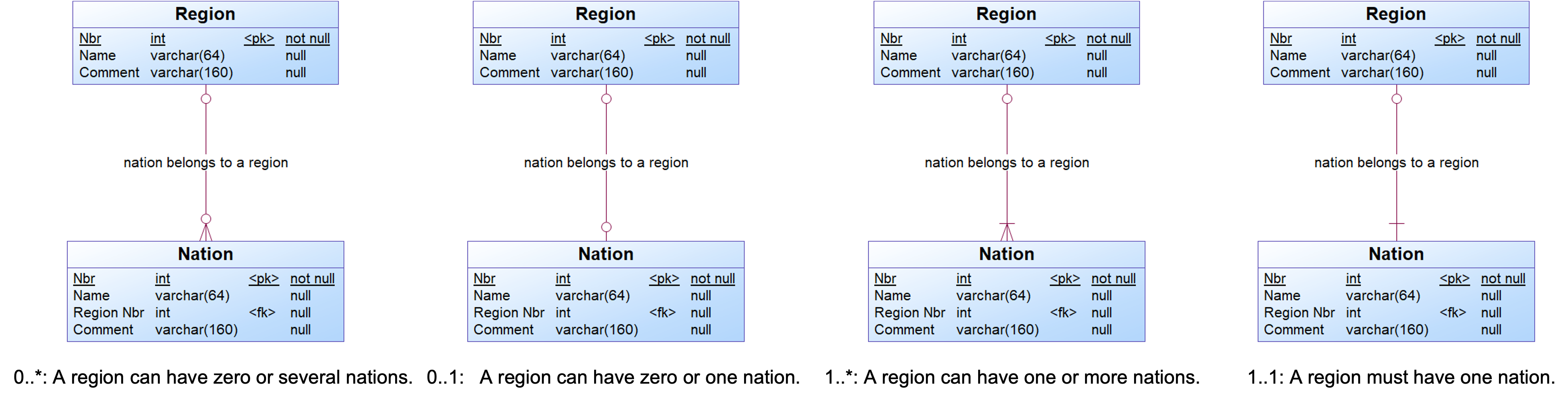
In a reference between two entities, one of them is the parent and the other is the child entity. For each reference, you can specify its cardinality, which can have one of the following values:
- 0..* : A parent can have zero or more children.
- 0..1 : A parent can have zero or one children.
- 1..* : A parent can have one or more children.
- 1..1 : A parent must have exactly one child
Besides the cardinality, additional properties can be specified to indicate if the participation of the parent entity is mandatory. When the parent is mandatory then the child entity is a dependent entity, and it relies on the parent entity for identification. In this case, the primary key of the parent entity is included in the child entity as a foreign key, and it becomes part of the primary key of the child entity. When the parent is not mandatory then the child entity is an independent entity.
{example} Consider the reference between the entities nation and region (region is the parent entity and nation is the child entity). This reference has cardinality 0..*, which specifies that an instance of the entity region can be related to none or several instances of nation. The participation of the parent entity (region) is not mandatory, i.e., it is possible to have instances of nation without a region.
The picture below illustrates the possible cardinality values for the reference between region and nation. In all cases, the participation of the parent entity is not mandatory.
Identifying constraints
Constraints are used to ensure the accuracy and the reliability of the source data. Constraints are identified based on the business requirements and can be classified as Built-in and Advanced. Built-in constraints are inherent to the data model and can be checked automatically, i.e. there is no need to perform additional steps to validate the inbound data delivery. Advanced constraints are added to perform validations at attribute, entity record, or entity set level.
The table below shows the different types of constraints, which can be used in a logical validation model to prevent non-compliant data from being further processed.
| Name | Type | How it works? |
|---|---|---|
| Datatype | Built-in | A datatype specifies the possible values for an attribute. When an attribute has different data types for the technical staging model and the logical validation model, then i-refactory checks if the data can be converted from the source datatype (datatype in the technical model) to the target datatype (datatype in the logical validation model). When it is not possible, the values of the violated constraints will be returned. |
| Mandatory value | Built-in | When an attribute is set as mandatory, the attribute must have a value. i-refactory will check if the attribute has a value. |
| Key | Built-in | When an attribute is set as a primary key, i-refactory will check if the primary key has a value and if this value is unique. When an attribute is set as an alternate key and a value is being populated, i-refactory will check if the alternate key value is unique. |
| Relationship | Built-in | When there is a relationship between two entities (parent and child entities) in the logical validation model then i-refactory will check: If the parent relationship exists: do the child entities have a parent entity? If the child relationship exists: does the parent entity have a child entity? |
| Enumeration | Advanced | Enumerations specify a list of values that an attribute may have. It can be applied to one specific attribute or to a domain. |
| Attribute value | Advanced | Attribute value constraints check whether the value of an attribute meets predefined conditions and can be assigned to one or more attributes. These constraints are formulated as a Should Comply To boolean expression. i-refactory uses this constraint as part of the validation process and gather statistic of non compliant attribute values. This will lead to a refused data delivered or it can help to identify data quality mismatches. |
| Entity-record | Advanced | Entity record constraints check whether an attribute meets the requirements set by another attribute. Entity record constraints use values of two different attributes from the same record to verify with regard to each other. |
| Entity-set | Advanced | Entity set constraints perform checks concerning the values of two or more attributes that belong to different entities or the value of an attribute with respect to a set of values (this happens when incoming data needs to be checked on existing data). |
{example} In our example, constraints about datatypes, primary keys and relationships are explicit in the diagram that represents the logical data model. Other validations are implemented as entity-set and entity-record constraints. An entity-set constraint is created to validate the value of the total order price of a given order (the value of the total order price of a given order should be equal to the value obtained when computing the total order price from the several order line items that compose the order). This validation is implemented through an entity-set constraint because values from different entities are compared. An entity-record constraint is created to make sure that the shipment date (ship date) of an order line item is less or equal to its receipt date.
Step 1. Adding an empty model
To start building a logical validation model, first you should create an empty logical validation model from a template, then the model will have all the necessary default settings. At any moment, you can perform a model check to verify if there are errors in the model.
Step 2. Creating entities
For each identified entity:
- Create an entity.
- Consider creating data domains to further unify your data.
- Add one or more attributes to the new entity.
- Adjust settings for valid time attributes: If the logical validation model uses valid times, these columns require special attention in order to be correctly treated in the runtime process as a bi-temporal entity.
- Add a primary key to the new entity.
- If necessary, create an index.
{tip} It is good practice to use domain types instead of a datatype. This is especially convenient when multiple attributes need to adhere to the same datatype and values. If the datatype or enumeration changes, you only have to adjust one domain instead of several attributes.
{info} If you use dates and times, it is important to know the differences between functional date, valid time, and transaction time.
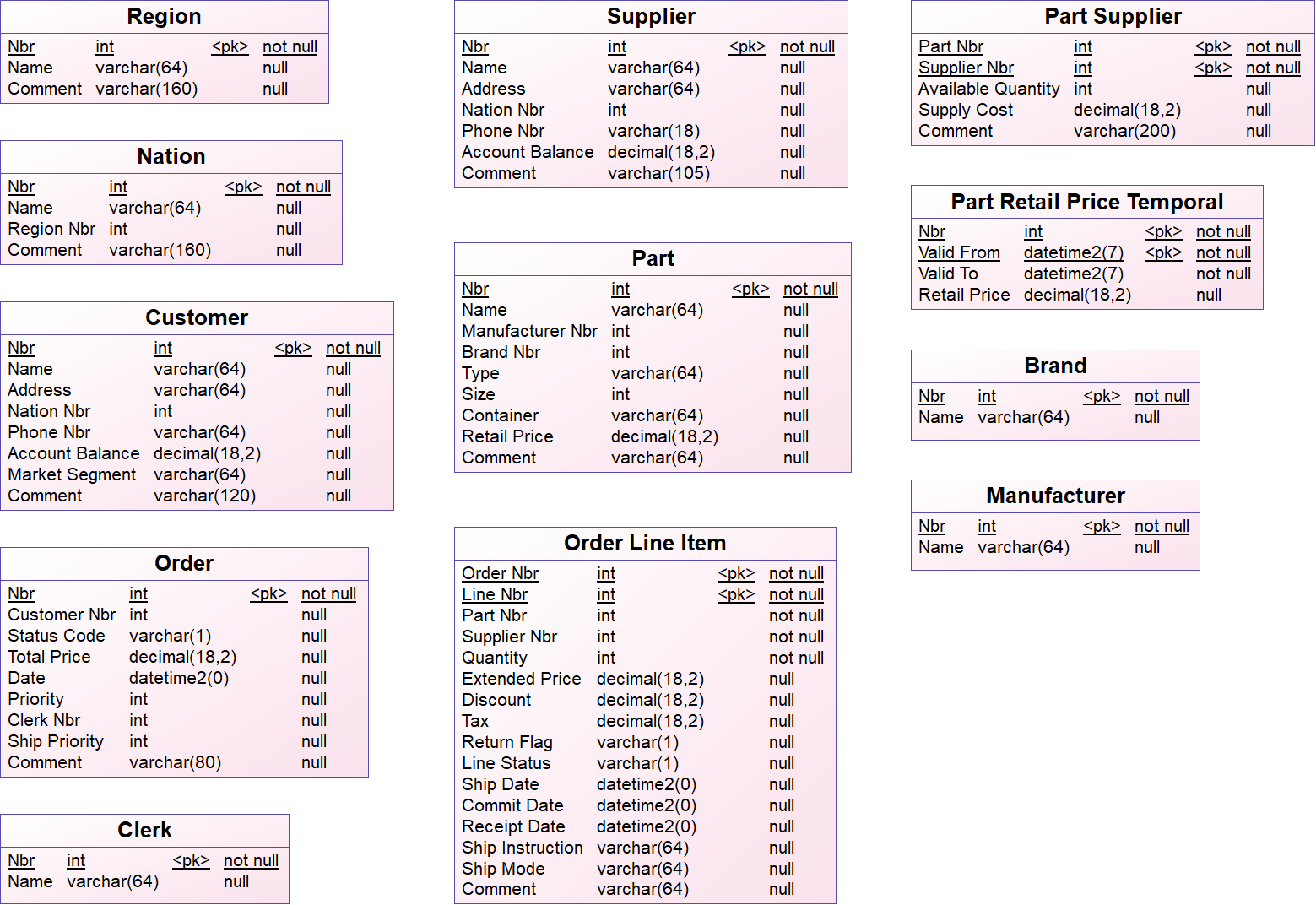
{example} In our example, the set of entities in the logical validation model is the same set of entities from the logical data model. But, when comparing the logical validation model with the technical staging model, you see three extra entities in the logical validation model: Clerk, Brand and Manufacturer. These entities are not explicitly represented in the technical staging model, but their information is hidden in the entities Orders and Part. There are also some differences in the name of entities (Orders, LineItem, PartSupp) and attributes because the naming in the logical validation model should follow the naming convention from the business requirements. The datatypes from attributes in the logical validation model also follow the logical data model.
Step 3. Adding references
For each identified reference:
- Add a reference from the child entity to the parent entity of the relationship.
- Indicate the cardinality of the reference, i.e. the minimum and maximum number of instances in a child entity permitted for each corresponding instance in the parent entity.
- Indicate if the parent is mandatory, i.e. each foreign key value in the child entity must have a corresponding key value in the parent entity (the child entity depends on the parent entity).
- If necessary adjust other properties of the reference.
{example} In our example, the references from the logical validation model are the same references from the logical data model.
Step 3.1. Change reference settings to create a context-based entity
This step is necessary when you have context-based partial deliveries and you need to change the reference settings to create a context-based entity. You need to create context-based entities when a set of data of a child entity may be delivered within the boundaries of a parent context. A context-based entity applies when:
- At least 2 entities are delivered.
- A context relationship exists between these 2 entities. One entity is the parent context of the other entity.
- The parent context entity is delivered as a delta and the child entity is delivered as a full set.
{example} It may happen that all the Part Suppliers for just one single Part number are delivered. Since there is only focus on the part that you specify in the delivery, all data of the other parts remains unchanged. To allow implicit delete detection and set based validations, the existing set of part suppliers must be filtered based on its parent context. Suppose that Part is delivered as a delta delivery and only parts
1,2,200are delivered. Part Supplier is delivered as a full load. This is what will happen:For the Part numbers
1,2,200we will do a full compare of the Part Supplier records between what is delivered and what is in CFPL.
- If a new key of Part Supplier is added, new records are added to Part Supplier.
- If a key of Part Supplier is delivered but attributes are altered, the record is updated.
- If a key of Part Supplier is not delivered, the record in CFPL is flagged as deleted.
- If you add a not yet existing Part number, it will be added as a record in Part.
- The constraints are also checked only for this context delivery. So, between the boundary of the context data.
- If you forget to set the context filter to
Trueand you make a partial delivery for only Part numbers1,2,200, than all other Part numbers will be deleted.
Another term used for this is context-based enddating, since it enddates records that are not taken into the delivery.
{warning} Do not forget to set the context filter in the central facts model as well. It is not automatically added.
Step 4. Creating subtypes and generalizations
When you identify subtype/supertype patterns and generalization patterns in the business requirements, you can use a supertype/subtype relationship in the LVM to capture them. You have two options to create a supertype/subtype relationship in a LVM:
- Create separate tables for each subtype (or specialization)
- Create a rollup table that contains all the attributes of the supertype (or generalization) and the attributes of the subtypes (or specializations)
{warning} Be aware that you need to implement keys in the generalized entity, although a strict generalized entity doesn't need to have keys.
Option 1: Create separate tables for each subtype
To generate subtypes as separate tables:
- If necessary, add an entity for each subtype as well as an entity for the supertype.
- Add a reference between each subtype and the supertype. The child entities (subtypes) have a zero-to-one relationship to the parent table (supertype).
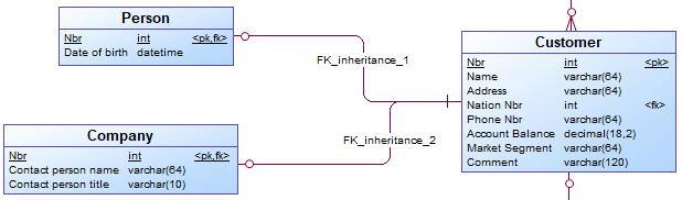
{example} Three separate entities (Customer, Person and Company) are used to represent the supertype/subtype relationship.
In the logical validation model it is possible to define subtype-supertype pattern as
Completeand/orMutual Exclusive.
Completepattern: all instances in the supertype can be found in the related subtypes. For example, a provider offers TV, internet, and phone plans, there are no other type of plans. A customer can choose to get a TV and internet plan, without a phone.Mutually exclusivepattern: one instance in the supertype can be found in none or just one Subtype. For example, a person can either be male or female.Mutually exclusive and completepattern: one instance in the supertype must be found in just one subtype. For example, a customer must either be a (natural) person or a company, there are no other types of customer available.
These patterns are not automatically implemented in the logical validation model or generated as metadata by i-refactory. To account for these patterns, you need to add set constraints to the logical validation model.
{warning} Depending on the type of subtype-supertype pattern (for example, mutually exclusive), the cardinality of the relationship between a subtype and supertype might not be correct. You need to adjust it accordingly.
Option 2: Create a rollup table
To create a rollup table containing all the attributes of the subtypes and the supertype:
- Create an entity for the supertype.
- Add all the attributes that are common to the subtypes and all attributes specific for each subtype to the supertype.
The attributes of the subtypes are rolled up into one table.
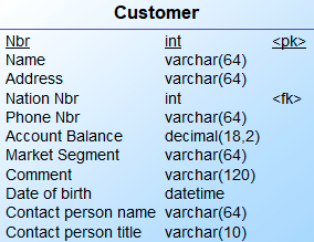
{example} Instead of having separate entities, you have only one entity (Customer), with the common attributes of Person and Company, as well as the specific attributes of each subtype.
Step 5. Adding advanced constraints
Advanced constraints are user-defined constraints, which can specify:
- constraints on values of an attribute or domain (enumeration or attribute value constraint)
- constraints on at least two attributes within one record (entity record constraint)
- constraints on at least one attribute within one or more entities (entity set constraint)
After creating these constraints, you need to attach them to the relevant attribute, domain or entity.
Step 5.1. Attribute value constraint
To add an attribute value constraint:
- Create the attribute value constraint.
- Assign the attribute value constraint to the relevant attribute(s).
{tip} If you want to use regular expressions to validate values, you need to add a .NET function. This website gives access to a .NET function to provide access to regular expressions (regex). For using regular expressions, first validate the query through regex101.
Step 5.2. Enumeration constraint
To add an enumeration constraint:
- Choose the attribute or domain whose value should be validated.
- Create the enumeration constraint.
{example} In our example, the number of a region must be between 0 and 4. To validate this, you create an enumeration constraint for the attribute Nbr of the entity Region.
Step 5.3. Entity-record constraint
Since Entity record constraints concern more than one attribute, they are assigned to an entity instead of an attribute. The regular expression is formulated as Should Comply To boolean expression.
Entity Record Constraints explicitly define the columns used - case sensitive. Columns are identified by their code.
To add an entity record constraint:
- Create the entity record constraint.
- Assign the entity record constraint to the relevant entity.
{example} In our example, there is a constraint that specifies that all records from Order Line Item for which the value of
Valid Fromis smaller than the value ofValid Toare returned.
Step 5.4. Entity-set constraint
To add an entity set constraint:
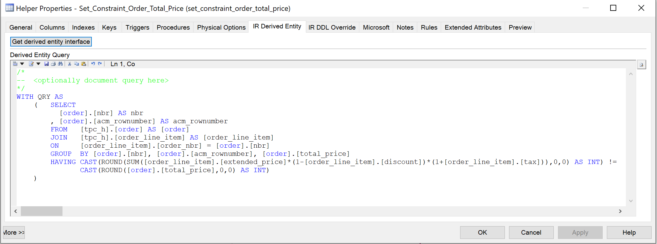
- Create a helper that contains a query which returns the records where the constraint is violated.
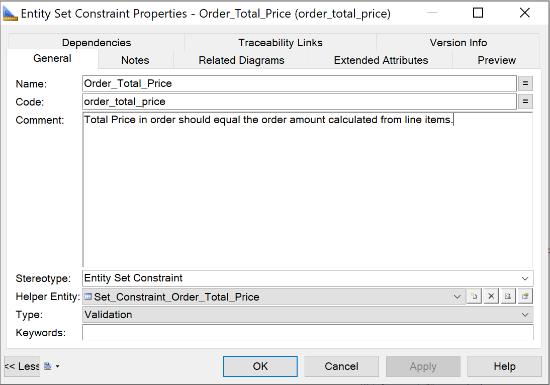
- Create an entity set constraint and assign the helper to this constraint.
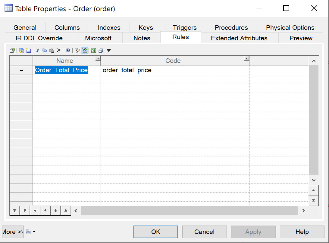
- Assign the entity set constraint to the relevant entity.
{info} An entity set constraint uses a set constraint helper, which needs to contain a query formulated as Identified as Incorrect. This means that it returns the set of records that are faulty, i.e., all records that do not comply with the constraint are returned. The choice to use Identified as Incorrect is based on performance. By selecting incorrect records directly, you avoid additional processing steps, such as comparing the correct records with the total set to determine the incorrect records.
{example} In our example, the value of total price of a given order should be equal to the total price of the order when calculated from its order line items. To validate this, there is an entity set constraint that returns all records from the entity Order that violate this requirement.
Step 6. Creating mappings
When you create a mapping between the technical model and the logical validation model, it is important to remember the following mapping rules:
- Generally, there is a one-to-one mapping between attributes from the technical model to the logical validation model.
- An attribute in the logical validation model must be mapped to one and only one attribute in the technical model. You can not concatenate multiple attributes from the technical model to the logical validation model.
- However, an attribute in the technical model can be mapped to multiple attributes in the logical validation model.
- An entity in the technical model can be mapped to multiple attributes in the logical validation model.
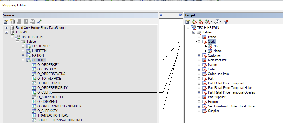
To create a mapping between entities or attributes from the technical staging model (source model) to the logical validation model (target model), first you need to select the source and target models. After this, you can create the mappings.
For each new entity in the LVM:
- Add a mapping between the corresponding entity or helper in the TSM and the new entity in the LVM.
- If necessary, add mappings between the attributes of the corresponding entity or helper in the TSM and the attributes of the new entity in the LVM.
Data type conversion: the data types of the mapped columns in a technical model and in a logical validation model do not necessarily have the same data type. The data type in a logical validation model can be stricter than the datatype in a technical model. When an attribute in a technical model is mapped to an attribute in a logical validation model, i-refactory explicitly converts the data to the datatype from the logical validation model.
{example} Suppose that in the technical model a date in ISO date format is provided as a string field:
8900-12-31. In the logical validation model, this field is modeled as a datetime2(7). At runtime, the loading process will execute aTRY_CASTon the string field as datetime2(7):8900-12-31 00:00:00.0000000.
Mapping of Primary key: when primary key columns from the source entity in the technical model are mapped to the corresponding target entity in the logical validation model, the uniqueness is checked when data is loaded in the Logical Validation Layer.
{warning} When there is no mapping between a primary key in the logical validation model and a primary key in the technical model, then a Distinct function needs to be used to generate uniqueness in the Logical Validation Layer.
Normalization: when the target model (LVM) is more normalized than the source model (TSM), i-refactory automatically normalizes the data if the entity is mapped to its normalized entities.
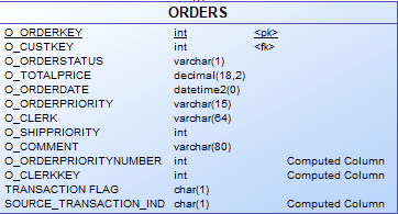
{example} The TPCH technical model has an entity
ORDERthat includes information about orders but also information about clerks. Such asO_ORDERKEY,O_ORDERSTATUS,O_CLERK,O_CLERKKEY. The clerk information is hidden in the entity and there will be duplicate clerk keys and clerk names in Order records. In the logical validation model, the data should be normalized and two entities should exist: one entity forOrderand one entity forClerk. The mapping can be made fromORDER.O_CLERKKEYin the technical model toClerk.Nbrin the logical validation model. Any key that is mapped in this scenario is automatically validated by calculating the distinct set.
{info} During a delivery the
DISTINCTis applied while loading the data into the normalized entity. If the denormalization ends up in key conflicts, you need to add a helper to the technical model to resolve the conflicts. This reflects an improved target model.
Step 7. Preparing for delta-loads
Additional mapping activities in the logical validation model are required to support delta-loads. Since a delta-load must indicate if a record is inserted (I), updated (U), or deleted (D), this information from the technical model must be transferred to the logical validation model.
For each entity for which a delta-load is expected:
- Apply the Staging Template to reveal the hidden metadata attributes.
- Map delta indicator from technical model to logical validation model
{warning} You need to make sure that the values in
ACM source transaction indicatorcorresponds toI,U, orD. The runtime processing through i-refactory uses this value as a given.