Start and stop the i-refactory Server
In this section we explain how to start and how to stop the i-refactory server.
General approach
Starting an i-refactory server
The i-refactory server is a NodeJS application which can be started on the command prompt from the root directory of the application.
cd <irefactory-root-application-directory>
export NODE_PATH=./
node src
In the above scenario the application is started and the assumption is made that a config.json file exists in the root application directory. The configuration file is read, some checks are executed and an attempt is made to connect to the database which contains the metadata repository.
If another i-refactory server is already running and connected to the same metadata repository the application startup will fail and exit. Only a single i-refactory server can be connected to a given metadata repository.
If you have several metadata repositories you can start an i-refactory server for each one of them. Simply pass a specific configuration file as a parameter and an attempt is made to start an i-refactory server with a connection to a specific metadata repository.
cd <irefactory-root-application-directory>
export NODE_PATH=./
node src <path>/<config file>
Stopping an i-refactory server
If the server is running in your terminal simply press Ctrl-C. This will result in a gracefull shutdown of the server. Existing tasks will be completed but new deliveries will not be accepted.
The terminate the i-refactory server immediately you need to force the server to stop. For example with: kill -9 <process-id>.
Starting the i-refactory as a background service
There are many ways to start the i-refactory server as a background service and there are many process managers. Perhaps the most easiest one is to create a docker container and start the service with a service manager for docker containers.
Docker example
Build an image
The i-refactory server is shipped as a zip file with the relevant node_modules already downloaded.\ Creating a docker image is straightforward.
Example Dockerfile:
FROM node:14-alpine AS dependencies
RUN apk update && \
    apk add --no-cache tzdata
ENV TZ Europe/Amsterdam

# Create app location
WORKDIR /app

# Copy code
COPY . .

# set the node path so modules can properly be required
ENV NODE_PATH=./- The alpine node docker image is the base image that is needed to run NodeJS.
- We install tzdata to set the server to the appropriate timezone.
- The content of the i-refactory server source files is copied to /app.
- The NODE_PATH is set to ./
To build the image open a terminal:
cd <directory where you stored the i-refactory server code>
create a file Dockerfile with the example content as shown above.
docker build -t  <image>:<tag> ./
Start a container with docker-compose
The i-refactory server can be started with docker-compose.
Example docker-compose file:
version: "3.8"
services:
  i-refactory:
    image: <your image>
    volumes:
      - <file-path-to-config-file>/config.json:/app/config.json:ro
      - <file-path-to-crypto-keys>:/app/crypto:ro
    ports:
      - 3000:3000
      - 3001:3001
      - 3002:3002
    # Needed to respond to prompts in the console
    stdin_open: true
    tty: true
    environment:
      - NODE_ENV=production
    command:
      node src
networks:
  default:
    external:
name: i-refactory-net- Uses docker 3.8 spec
- Defines a service with name i-refactory for the image that was build with the Dockerfile. You need to replace
. - With the volumes section you need to pass the config.json file and the crypto files.
- Port mappings for the different i-refactory services
- A default network is created. Rename if needed.
To start the i-refactory server with docker-compose:
# Create a file docker-compose-irefactory.yml and store your compose config in it.
docker-compose -f ./docker-compose-irefactory.yml up -d
If the i-refactory server doesn't seem to start:
docker attach <the running container>
# and enter yes
Note: if a new version is shipped and the server is started console input is required to specify if an upgrade is allowed. In future versions we will remove this console input and replace it with an environment variable.
Start the i-refactory server on Windows with NSSM
To download and install NSSM and for more information see nssm.cc
Installing the service manually
Create the i-refactory-server service from the command line:
nssm install "<your-service-name>"
This starts the installer, which consists of several tabs with lots of configurable parameters. The most import parameters are discussed below.
Application tab
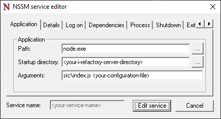
{list}
- Enter the Path to your Node.js executable.
- Enter the Startup directory of your i-refactory-server installation.
- Enter the
src\index.jsscript and the configuration file to use as the Arguments.
Details tab
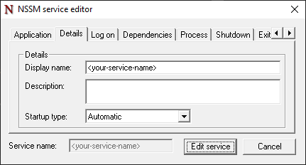
{list}
- Select the correct Startup type.
- Optionally alter the Display name of the service in the services app and enter a Description.
Shutdown tab
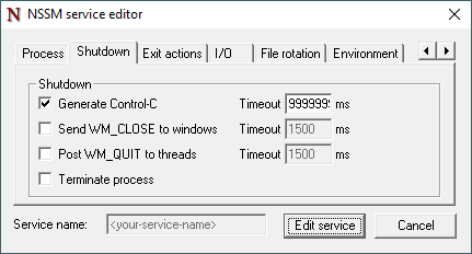
The Shutdown tab determines how NSSM attempts to stop the i-refactory-server.
{list}
- Select the Generate Control-C option and enter a ridiculously high Timeout to ensure the service state reflects the state of the i-refactory-server when the service is stopped. For example enter 86.400.000 ms to indicate a timeout of one day.
- Deselect the Send WM_CLOSE to windows option.
- Deselect the Post WM_QUIT to threads option.
- Deselect the Terminate process option.
Exit actions tab
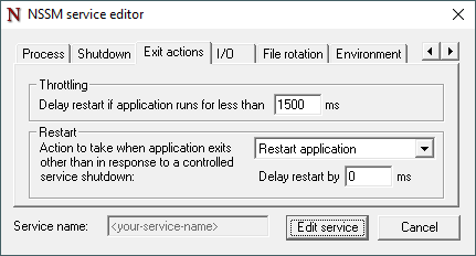
The Exit actions tab determines how NSSM attempts to restart the i-refactory-server when the i-refactory-server stopped unexpectedly.
{list}
- Select the Restart action to take when the i-refactory-server stopped unexpectedly.
- Optionally set the Restart Delay restart option.
- Optionally set the Throttling Delay restart option. This will increase the time between restarts when the i-refactory-server keeps stopping unexpectedly, for example because no connection can be made to the database.
I/O tab
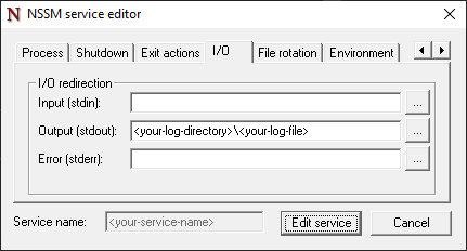
{list}
- Enter the location and file name for the Output logging.
File rotation tab
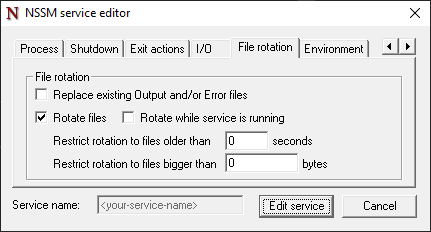
The File rotation tab can be used in conjunction with I/O settings to configure rotation of output files when the service restarts.
To create new output files every time the i-refactory-server service is started:
{list}
- Deselect the Replace existing Output and/or Error files option.
- Select the Rotate files option.
- Deselect the Rotate while service is running option.
- Set the Restrict rotation to file older than option to 0 seconds.
- Set the Restrict rotation to file bigger than option to 0 bytes.
Existing files will be renamed according to a template which uses the last modification time of the file.
Environment tab
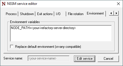
{list}
- Enter the location of your i-refactory-server installation as NODE_PATH.
Installing the service using a script
The service can also be configured from the command line or with a script. The service displayed in the examples is created with the following script.
nssm install "<your-service-name>" "node.exe"

nssm set "<your-service-name>" AppDirectory "<your-i-refactory-server-directory>"
nssm set "<your-service-name>" AppParameters "src\index.js <your-configuration-file>"
nssm set "<your-service-name>" AppStopMethodSkip 14
nssm set "<your-service-name>" AppStopMethodConsole 999999999
nssm set "<your-service-name>" AppExit Default Restart
nssm set "<your-service-name>" AppRestartDelay 0
nssm set "<your-service-name>" AppStdout "<your-log-directory>\<your-log-file>"
nssm set "<your-service-name>" AppRotateFiles 1
nssm set "<your-service-name>" AppEnvironmentExtra NODE_PATH="<your-i-refactory-server-directory>"
nssm set "<your-service-name>" Start SERVICE_AUTO_START
Graceful shutdown
The i-refactory-server can be stopped like any other service using the Services app. As long as logical validation deliveries and/or metadata imports are being processed, the status of the i-refactory-server will remain running and the service will have status Stopping. This is reflected in the logging with a message i-refactory is closing.
When all logical validation deliveries have reached an end state and all metadata imports have been processed, the i-refactory-server exits and the service will have status Stopped. This is reflected in the logging with a message i-refactory is stopped.
The following options on the Shutdown tab might influence the graceful shutdown:
- Generate Control-C Timeout
- Terminate process
The Generate Control-C Timeout determines how long MSSN will wait for the i-refactory-server to exit. This is the reason why the timeout should be set to a ridiculously high timeout to ensure the i-refactory-server can gracefully shutdown.
When the timeout expires and the i-refactory-server has not exitted there are two options:
- The service is marked as stopped while the i-refactory-server is still running.
- The i-refactory-server is terminated by MSSN.
This is determined by the Terminate process option:
- When the option is selected then the i-refactory-server is terminated.
- When the option is deselected then the service is marked as stopped, but the i-refactory-server remains running.
Non-graceful shutdown
When the service is configured in such a way that the i-refactory-server is restarted when it exits unexpectedly, and the i-refactory-server should be stopped immediatelly - i.e. without waiting for all logical validation deliveries to be processed, etc. - then the following instructions should be followed:
{list}
- Stop the service using the Services app. The i-refactory-server might exit immediatelly and the service is stopped.
- If the service is not stopped immediatelly you can kill the Node.js process in the Task Manager. This will stop the service without restarting the i-refactory-server.
If multiple Node.js processes are running, you can check the logging for the pid. The pid is logged with a message i-refactory is running, pid <nnn>.