How to generate a logical validation model from a logical data model
In this section you can find how to generate a logical validation model (LVM) from a Logical Data Model (LDM), when a LDM is available. This speeds up your work and ensures you use the exact definitions as specified in the LDM. Another advantage is having lineage on all physical data models. For example, if you alter an attribute in one model, you can evaluate the impact of this change. In another section we explain how to create a logical validation model from scratch.
At any moment, you can perform a model check to verify if there are errors in the model.
When you update a LDM, you can also update a logical validation model that is already linked to it.
Before you begin
Before generating the logical validation model, make sure that the LDM has the following requirements:
- Each entity must have a primary key.
- Relations are defined and cardinality settings are correct.
- Each attribute has a datatype.
Step 1. Generating a LVM from a LDM
To generate a logical validation model from a LDM:
-
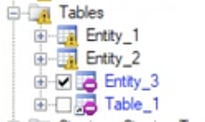
Create an empty logical validation model from a template or open an existing empty logical validation model.
-
Open the LDM from which you want to generate a logical validation model.
-
In the active LDM, go to
Tools > Generate Physical Model.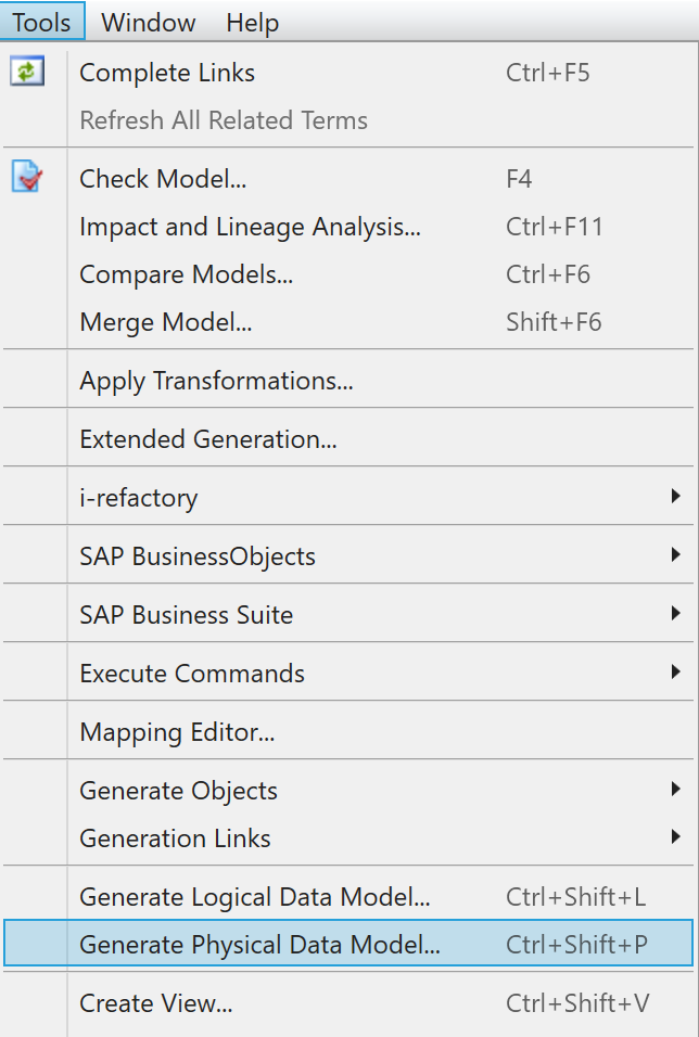
Menu Generate Physical Data Model -
In the tab
General, selectUpdate Existing Physical Data Model.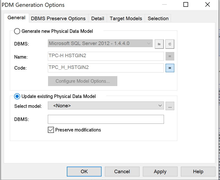
Menu Update Existing Physical Data Model -
Select the option
Preserve modifications. This ensures that the adjustments to the logical validation model will not be overwritten by the LDM, but are preserved. -
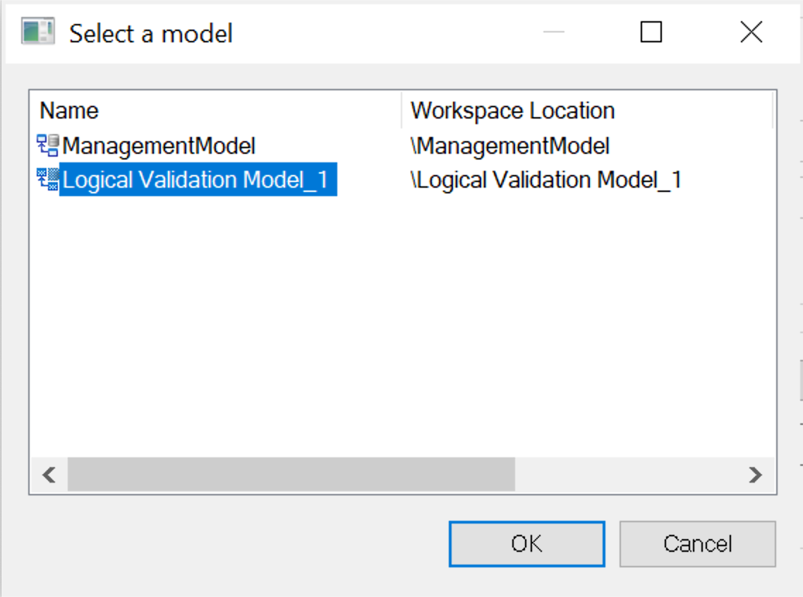
If there is no Physical Data Model next to
Select model, you can select the logical validation model. Click on the button with.... -
Go to the tab
Detail. -
Go to the tab
Selection. -
You can choose which entities you want to add. Tick the check box next to the entities you want to add.
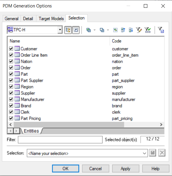
Menu PDM generation options -
Press OK.
-
The
Merge Modelwindow appears. In this window, you can configure how the two models are merged.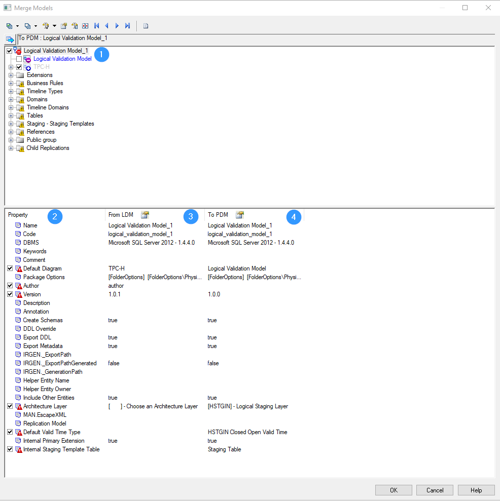
Merge models window -
The root model is displayed at the top of the window (
1). In the example above, this is the physical data model, calledLogical Validation Model. -
The properties of the models to be merged are displayed at the bottom half of the window:
- Property (
2): name of the settings - From LDM (
3): details of the LDM - To PDM (
4): details of the physical data model
- Property (
-
There are also several icons:
- Notification that children were modified:

exclamation mark yellow - Notification that object properties were modified:

exclamation mark red - If selected, this object will be deleted:

minus symbol - If selected, this object will be added:

plus symbol
{info} Visit the PowerDesigner online manual for more information about the Merge Action Icons.
- Notification that children were modified:
-
In the
Merge Modelwindow, unselect the following options:Architecture Layer: The architecture layerHSTGIN-Logical Staging Layerof the logical validation model must be kept.Default Valid Time Type: The settings of the logical validation model must be kept.Internal Staging Template Table: The settings of the logical validation model must be kept
-
When you create an empty logical validation model, the standard version is 1.0.0. Select the box next to
Versionif you want to import theVersionvalue of the LDM to the logical validation model. -
Unselect
Timeline types. Otherwise, these timeline types will be deleted in the logical validation model.
-
-
After having carefully checked the options, click on
OK. -
In the logical validation model a new diagram appears. This new diagram has the same name as the diagram in the LDM. You can rename the diagram.
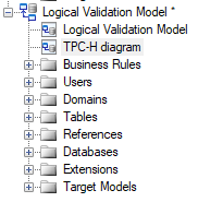
TPC-H diagram -
To solve the classification property error, save the logical validation model, close it en reopen it again.
{warning} Be very careful in the Merge Model settings. Especially when updating an existing logical validation model. PowerDesigner will automatically select several options from the configuration of how the two models will be merged. Carefully check the settings. Otherwise these settings will overwrite the i-refactory settings in the logical validation model, which will lead to errors. Fortunately, PowerDesigner will not delete objects by default.
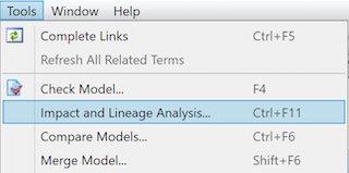
After you have generated the logical validation model from the LDM, a relation is established between the two models.
This means that if you change some properties in the LDM, you can use the option Impact and Lineage Analysis... to check which entities and which models will be affected by the change. You can also check which models are linked to the LDM.
Step 2. Post-processing the generated logical validation model
After the automatic generation of the logical validation model, there are some extra settings or steps that you need to follow. You do this to make sure that the logical validation model is in accordance with the logical data model and to avoid errors during the runtime process.
Step 2.1. Adjusting the datatypes
The automated generation of the logical validation model requires a post-processing before you can continue.
The datatypes in the LDM are different from the datatypes in a physical data model, such as the logical validation model. For example, a datetime in a LDM needs to be changed to a datetime2 datatype in the logical validation model, because the datatype in the SQL Server database needs to be more precise than in the LDM.
{tip} To update the datatypes of multiple attributes at the same time, you can use the option show the properties of all attributes in the model.
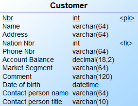
{example} You can see the differences in datatypes between attributes of the entity Order in the LDM and the entity Order in the LVM.
Integeris correctly changed tointVariable characters (64)is correctly changed tovarchar(64)Decimal(18,2)is correctly changed todecimal(18,2)However, there are some datatypes that require your attention:
- Date: dates should be changed to the datatype
Date.- Date & Time:
Date & Timeshould be changed todatetime2. Make a conscious choice about what precision you need. Precision 0 (zero) means it includes seconds. With precision 7 it includes nanoseconds. For valid time, you need to select the datatypedatetime2(7).- Variable characters: make sure to check if the datatype has to be
varchar(%n)ornvarchar(%n).

Step 2.2. Creating subtypes and generalizations
When the LDM contains subtype/supertype patterns or generalization patterns, you are required to do extra configuration to determine what entities should be generated in the logical validation model. In the logical validation model, both patterns can be captured using a supertype/subtype relationship.
To create a supertype/subtype relationship in the logical validation model, you have two options:
- Create separate tables for each subtype (or specialization)
- Create a rollup table that contains all the attributes of the supertype (or generalization) and the attributes of the subtypes (or specializations)
Option 1: Separate tables for each subtype
In this case a subtype is implemented in the logical validation model as an entity with a zero-to-one relationship to the supertype entity. To generate the subtypes as separate tables, you need to:
- Select the options
Generate ChildrenandGenerate Parentin theInheritance Propertiesof the LDM.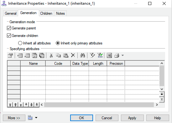
Inheritance properties - For every subtype, an entity is generated. The child entities have a one-to-one relationship to the parent entity.
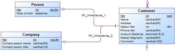
Separate tables for each subtype
In the logical validation model it is possible to define subtype-supertype pattern as
Completeand/orMutual Exclusive.
Completepattern: all instances in the supertype can be found in the related subtypes. For example, a provider offers TV, internet, and phone plans, there are no other type of plans. A customer can choose to get a TV and internet plan, without a phone.Mutually exclusivepattern: one instance in the supertype can be found in none or just one Subtype. For example, a person can either be male or female.Mutually exclusive and completepattern: one instance in the supertype must be found in just one subtype. For example, a customer must either be a (natural) person or a company, there are no other types of customer available.
These patterns are not automatically implemented in the logical validation model or generated as metadata by i-refactory. To account for these patterns, you need to add set constraints to the logical validation model.
{warning} Depending on the type of subtype-supertype pattern (for example, mutually exclusive), the cardinality of the relationship between a subtype and supertype might not be correct. You need to adjust it accordingly.
Option 2: Rollup table
To create a rollup table containing all the attributes of the subtypes, you need to:
- Select the option
Generate Parentin theInheritance Properties.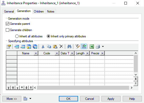
Inheritance properties - The attributes of the subtypes are rolled up into one table.
Rollup table
Step 2.3. Adjusting settings for valid times
When the logical validation model uses valid times these columns require special attention in order to be correctly used in the runtime process. For each column that is treated as valid time you need to adjust settings for valid times.
Step 2.4. Adding advanced constraints
You can also add constraints to the logical validation model to reflect the business requirements and to validate the data.
Updating a linked logical validation model
If you've already linked the LDM to the logical validation model, you can merge the models again after making changes in the LDM. You need to be very careful in the Merge Model window and analyse every option.
If you add an attribute, entity or business rule to the LDM, or delete an object from the LDM, the procedure is almost the same as generating a new logical validation model.
- Click on
Tools > Generate Physical Data Model. - Select
Update existing Physical Data Model. The linked logical validation model is already selected.
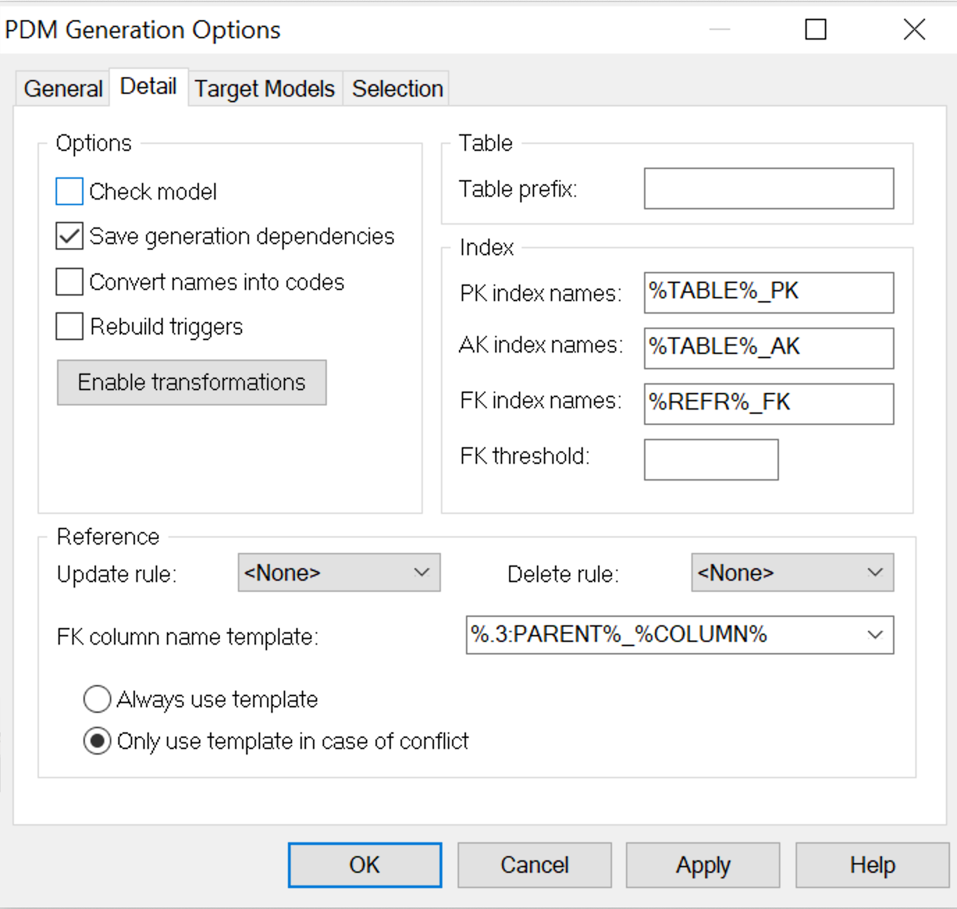
PDM Generation Options - Click on
OK. -
The window
Merge Modelsappears.- Unselect
Architecture Layer. The architecture layer[HSTGIN]-Logical Staging Layerof the logical validation model must be kept. - Unselect
Default Valid Time Type. The settings of the logical validation model must be kept. - Unselect
Internal Staging Template Table. The settings of the logical validation model must be kept. - Carefully check every option. Sometimes the code of an attribute changes to uppercase instead of lowercase.
- If you select an entity that need to be deleted, the foreign key will also be deleted.
{warning} Shortcuts to tables in the
Merge Modelswindow represent mappings to the technical model. Don't delete these mappings. - Unselect
- If necessary, update the datatypes of the logical validation model
- To solve the classification property error: Save the logical validation model, close it en reopen it again.